

Rutherford used two principal methods of measuring the intensity of the radiations emitted by a radioactive substance. A gold-leaf electroscope comprised a metal box containing an insulated metal rod, R, to which was attached one end of a gold leaf, L (Fig. 1). When the rod was charged, by connecting it momentarily to a battery of 200-300 volts, the gold leaf was repelled (since like charges repel) and its separation from the rod could be viewed by a telescope, fitted with a scale, through two holes in the outer box covered with thin mica. Ionizing radiation discharged the rod and leaf, so that the leaf gradually returned to its original vertical position in contact with the rod, and the rate of fall of the leaf was a measure of the intensity of the radiation. The gold-leaf electroscope was an extremely sensitive instrument and could measure tiny amounts of radiation.(4)
The gold-leaf electroscope could be activated directly by β or γ radiation entering through a window in the outer metal container. For the measurement of α-rays, Rutherford devised a combined ionization chamber and electroscope (Fig. 2) in which a layer of the active material was spread on Plate P and the parallel plate P' was connected directly to the rod L' of the electroscope.(4) An instrument of this type is included in Cabinet A. (Exhibit A-4, see next page.) Two further applications of the gold-leaf electroscope are shown in Cabinet D. (Exhibits D-3 and D-4, see next pages.)
An alternative measuring instrument was the quadrantelectrometer, used in conjunction with an ionization chamber. The electrometer comprised a flat cylindrical metal box divided into four insulated quadrants. A light metal paddle ("needle") was suspended inside the quadrants by a thin wire and movement of the needle could be observed on a scale by a light beam reflected by a small mirror attached to the suspending wire. One pair of opposite quadrants was connected to earth, the other pair to the electrode B of an ionization chamber (Fig. 3). The ionization current in the chamber altered the potential of the electrode and hence of the quadrant pair to which it was connected. This resulted in a movement of the needle which, translated into deflection of the light beam on the scale, could amount to as much as 10 cm per volt.(5) A particularly sensitive quadrant electrometer was that devised by Dolezalek in 1901,(6) as exhibited in showcase D (see next pages).
For working with a quadrant electrometer, it was found necessary to use a special remote-control key (K in Fig. 3) for making and breaking the connection to earth of the quadrants. The key shown in (Fig. 4) and displayed in Cabinet D comprised a brass tube B, which could be moved up and down within a rigid support A, thereby making or breaking contact with mercury M within an ebonite cup. The movement was controlled at a distance by the cord C, together with overhead pulleys.(7)
Both the gold-leaf electroscope and the quadrant electrometer registered radiation intensity in terms of a rate of movement, either of the gold leaf or of the needle. This was a somewhat slow and cumbersome procedure, and could be used only if the radiation intensity remained sensibly constant throughout the measurement. However, some elements in the radioactive series decayed very rapidly, with half-lives of minutes or even seconds. A null method of measurement was therefore needed, in which a constant deflection of the electrometer needle, proportional to the radiation intensity was obtained. This problem was solved by Bronson in 1905, by balancing the unknown ionization current against a constant current generated in a second parallel-plate chamber in which the lower plate was coated with a layer of radioactive material of long half-life.(8) A modification of this instrument was devised by Allen in 1907,(9) and this instrument is displayed in Cabinet D (see next pages).
Rutherford also measured other properties of the radiations emitted during radioactive transformations, including their photographic and heating effects, but only ionization could be measured quantitatively with a high degree of accuracy.


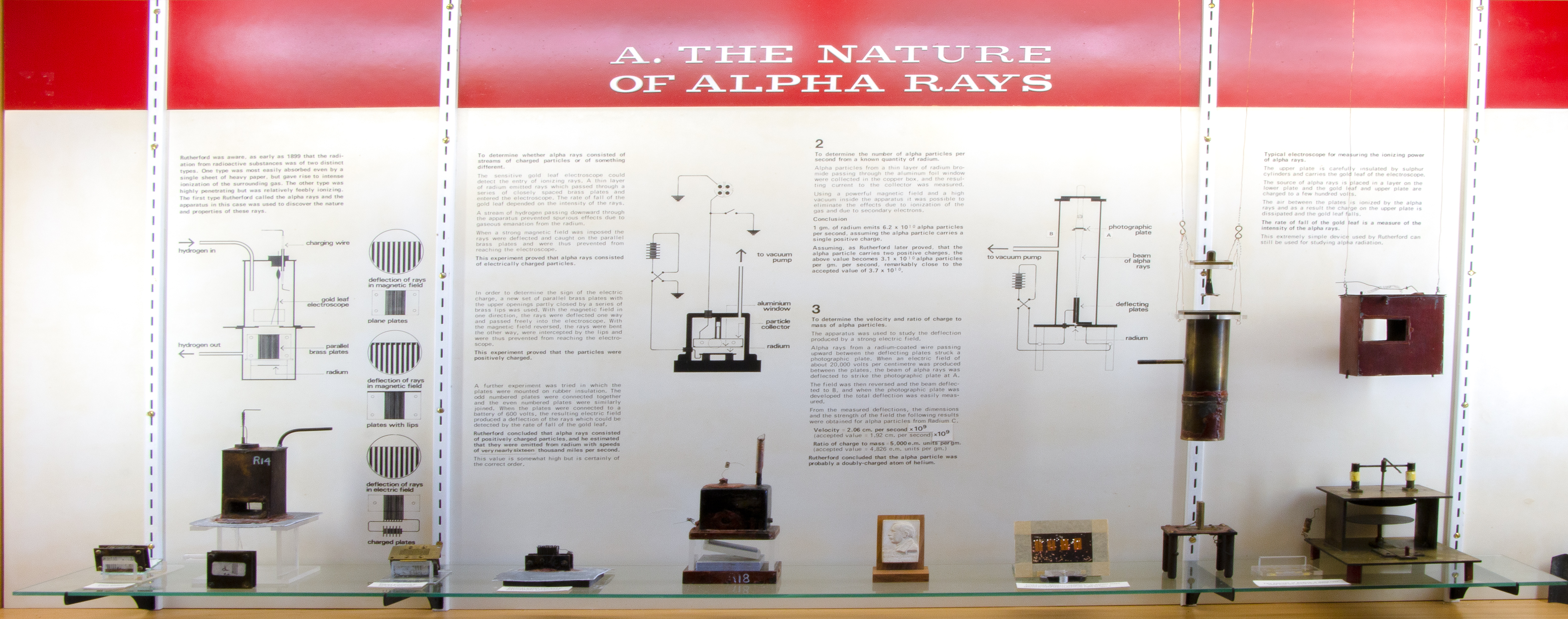
Rutherford discovered the heterogeneous nature of the radiation emitted by radioactive materials in 1898, whilst he was still a graduate student in Cambridge.(10) He called the readily absorbed component α-rays and the more penetrating component β-rays. (The γ-rays were discovered in 1900 by Paul Villard in Paris.(11)) The particulate nature of the β-rays was easily demonstrated, since they were deflected in electric and magnetic fields, but, prior to 1902, the nature of the α-rays was unknown. It was assumed that they were charged particles, but this was unproven because they could apparently not be deviated in a magnetic or electric field. Rutherford suspected that a very strong field was needed to deviate the α-rays and he designed the apparatus accordingly.
A-1. Magnetic and electrical deviation of the α-rays (Figs. 5,6):
The α-rays from a layer of radium salt passed through a set of parallel brass plates into a gold-leaf electroscope. A stream of hydrogen through the electroscope minimized the effect of emanation from the unscreened radium. When a strong magnetic field from an electromagnet (borrowed from the Electrical Engineering Dept.) was applied across the plates the reading of the electroscope (rate of fall of the leaf) substantially decreased. Similarly, by connecting the plates alternately to the positive and negative poles of a powerful battery, deviation in an electric field could be demonstrated. This proved that the rays were charged particles. By half-covering the exits to the parallel plates, such that the open portion was to one side, the direction of the deviation, and hence the sign of the charge, could be determined. This showed that the particles were positively charged, and fairly good values of the ratio of their charge to mass, and velocity, could be deduced. (Rutherford, 1903, Ref. 12)
A-2. Charge carried by the α and β-rays (Fig. 7):
In 1904 Rutherford measured the total charge carried by the a particles emitted by 0.19 mg of radium bromide solution, which had been evaporated to dryness, thereby expelling the emanation, and spread as a very thin layer on a plate. The α-rays were collected in a copper collecting vessel. A strong applied magnetic field and a high vacuum inside the vessel eliminated the effects of gaseous ionization and secondary electrons. The charge collected was measured by a quadrant electrometer. Assuming that the a particle carries a single ionic charge, Rutherford calculated from the measurements that 1 g of pure radium expels 6.2 x 10¹⁰ α-rays per second in the absence of decay products, and four times this number when in radioactive equilibrium with its products. The 'pure' radium constant reduces to 3.1 x 10¹⁰ per second on the basis of a double ionic charge carried by each a particle; the accepted value is now 3.61 x 10¹⁰. (Rutherford, 1905, Ref. 13)
The same apparatus was used to measure the rate of b emission from the active deposit on a lead rod exposed for 3 hours to radium emanation (radon). The β-rays were emitted solely by the radium C in the deposit, while the α-rays were completely absorbed by a thin foil of aluminum. The experiment indicated that 1 g of radium emitted 7.3 x 10¹⁰ b particles per second, a number commensurate with that obtained for a particles. From these values Rutherford calculated the half-life of radium to be 1280 years. (The accepted value is now 1620 yr.)
A-3. Velocity, and ratio charge/mass, of the a particle (Fig. 8):
Rutherford used this apparatus in 1906 to verify his assumption that the mass, and ratio of charge to mass, of all a particles is the same. This required the determination of e/m for different line sources of a particles, derived from radium A (218Po), radium F (210Po), actinium and thorium. The value of e/m obtained in each case was the same, within the (fairly large) experimental error. Furthermore, e/m remained unchanged (again, within the experimental error) after the particles had passed through screens of mica and aluminum equivalent to 6.5 cm of air. After emerging from the deflecting plates the α-rays reached a small photographic plate and, with a very long exposure (several days) gave an image of the line source. By reversing the voltage at intervals the image was split into two, the separation of which depended on the voltage and the geometry of the apparatus. A voltage of 500 V and a gap of 0.21 mm between the plates resulted in images about 2 mm apart.
By careful measurement of the image separation Rutherford was able to calculate mu2/e, where u is the velocity of the particle in passing between the plates.(Rutherford, 1906, Ref. 14) The deviation in a magnetic field (Exhibit A-1) gave values of mu/e, so the two results together enable u and e/m to be calculated. The value of e/m thereby obtained was 5.1 x 10³ electromagnetic units, half that of the hydrogen ion (104) obtained by hydrolysis of water. Rutherford listed three possible identities of the a particle consistent with this finding; his preferred identity was that of a helium atom carrying twice the ionic charge of hydrogen, but the final proof of this had to wait until 1908, when he had moved to Manchester and was able to carry out an experiment in which the identity of helium was demonstrated spectroscopically.(15)
A-4. α-ray electroscope (Fig. 2):
As discussed above, under "Measurement techniques," this apparatus is a combined parallel-plate ionization chamber connected directly to a gold-leaf electroscope contained within a single metal box. The α-emitting radioactive layer was spread on the lower electrode. The gold leaf itself is missing.(16)


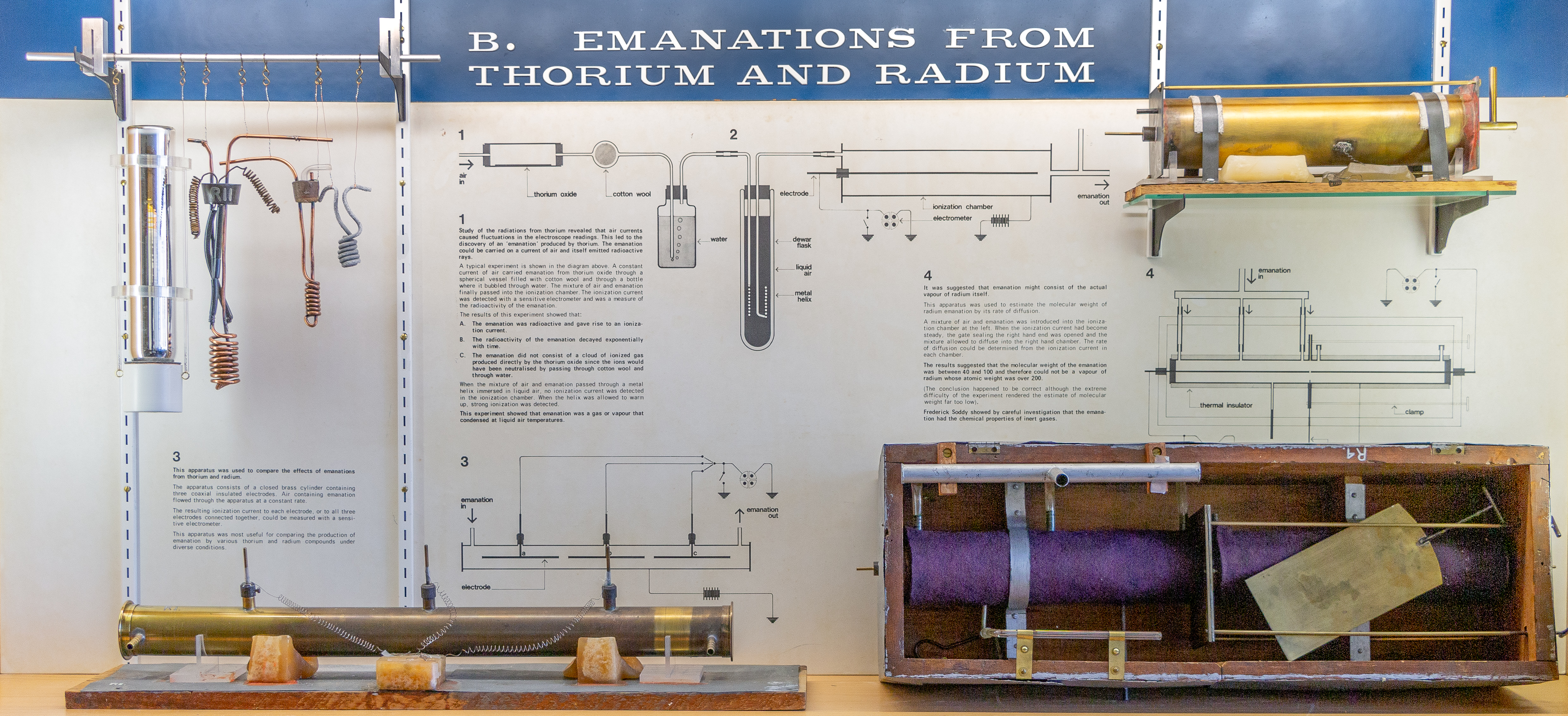
In 1899 Rutherford observed that the radiation from thorium oxide was not constant, but "varied in a most capricious manner." If the substance was enclosed in a lead box with a door, the rate of leak of the gold-leaf electroscope was much slower with the door open than closed. The compounds of uranium, on the other hand, remained constant. Rutherford concluded that thorium compounds continuously emit radioactive particles which retain their radioactive powers for several minutes. Rutherford called this emission 'emanation'.(17) At about the same time Pierre and Marie Curie observed a similar phenomenon with radium, except that the 'gas' emitted by radium remained radioactive for a month.(18)
The pieces of apparatus in this cabinet are not arranged in chronological order. The earliest (1901) is item B-4, while B1/2 dates from 1902-03.
B-1 and B-2. Condensation of thorium emanation (Fig. 9):
A current of air, passing through a tube containing thorium oxide, carried thorium emanation through a copper helix and then into an ionization chamber, producing a current which was detected by an electrometer. Any ionized gas produced directly by the thorium was removed in the vessels containing cotton wool and water. When the metal helix was immersed in liquid air in a Dewar (thermos) flask, the reading of the electrometer ceased, indicating that the emanation had condensed at the low temperature in the flask. After removing the helix from the flask the ionization current gradually returned as the emanation was restored to a gaseous state. The temperature at which the emanation condensed was determined by measuring the voltage across the helix when a constant current was sent through it, and hence calculating its resistance.(Rutherford and Soddy, 1903, Ref. 19) The helix used for this purpose is displayed in Cabinet E (see below). The condensation point of thorium emanation was found to be about -120°C, while that of radium emanation was about -150°.
B-3. Measurement of thorium emanation (Fig. 10):
The apparatus shown in the diagram was used to study the emanating power of different compounds of thorium and to measure the rate of decay of the emanation. (Only the cylindrical ionization chamber is displayed.) The substance under study, in the form of a fine powder, was placed in the glass cylinder C and a current of air from a large gas-bag was passed through the cylinder. The sulfuric acid (A) and cotton-wool (D) removed dust particles, spray and charged particles carried with the emanation. The three electrodes E, F and H were of equal length and located on the axis of the ionization chamber, and an insulating key was arranged such that any one of the electrodes, or all three together, could be connected to the electrometer. With an air current flowing at about 0.8 cm/sec the current to electrode E was about twice that to electrode H, and this corresponded to a half-life of about 1 minute for thorium emanation. The apparatus was used to compared the emanations from different compounds and specimens of thorium.(Rutherford and Soddy, 1902, Ref. 20 and 21.)
B-4. Determination of molecular weight of radium emanation (Fig. 11):
At first it was thought that emanation was simply thorium or radium in vapor form, but the amount available was far too small to carry out chemical, or even spectroscopic, tests. Rutherford therefore decided in 1901 to estimate the molecular (or atomic) weight of radium emanation by measuring its rate of diffusion in air. (He used radium, rather than thorium, emanation because the former had a reasonably long half-life, about 4 days, and was therefore approximately constant throughout the experiment.) The long cylindrical ionization chamber was divided into two by a sliding metal gate. With the gate closed, air containing emanation was passed into the left-hand chamber and readings of the ionization current made with the electrometer. When the electrometer reading became constant (indicating that the emanation was uniformly distributed in the chamber), the supply of emanation was stopped, the entrance and exits for the air closed, and the sliding gate opened. Electrometer readings were now made for the right-hand chamber, and those on the left were continued.
Eventually the two chambers showed equal ionization currents, indicating that the emanation was uniformly distributed between the two chambers. Analysis of the time sequence (on the basis of the kinetic theory of gases) indicated that the molecular weight of the emanation was between 40 and 100.(22) This showed that the emanation could not be radium in vapor form since Mme. Curie had already shown that radium was an element of atomic weight at least 140.(23) Actually this result was quite wrong - the experiment was subject to many errors and uncertainties. If Rutherford had obtained the right answer (222) and had known that the atomic weight of radium is 226, he might have concluded that the emanation was indeed radium vapor. As it was, the result constituted an important piece of evidence supporting the transmutation theory, which was beginning to take shape in his mind. In this experiment Rutherford was assisted by a young graduate student, Harriet Brooks, a biography of whom was published in 1992.(24)


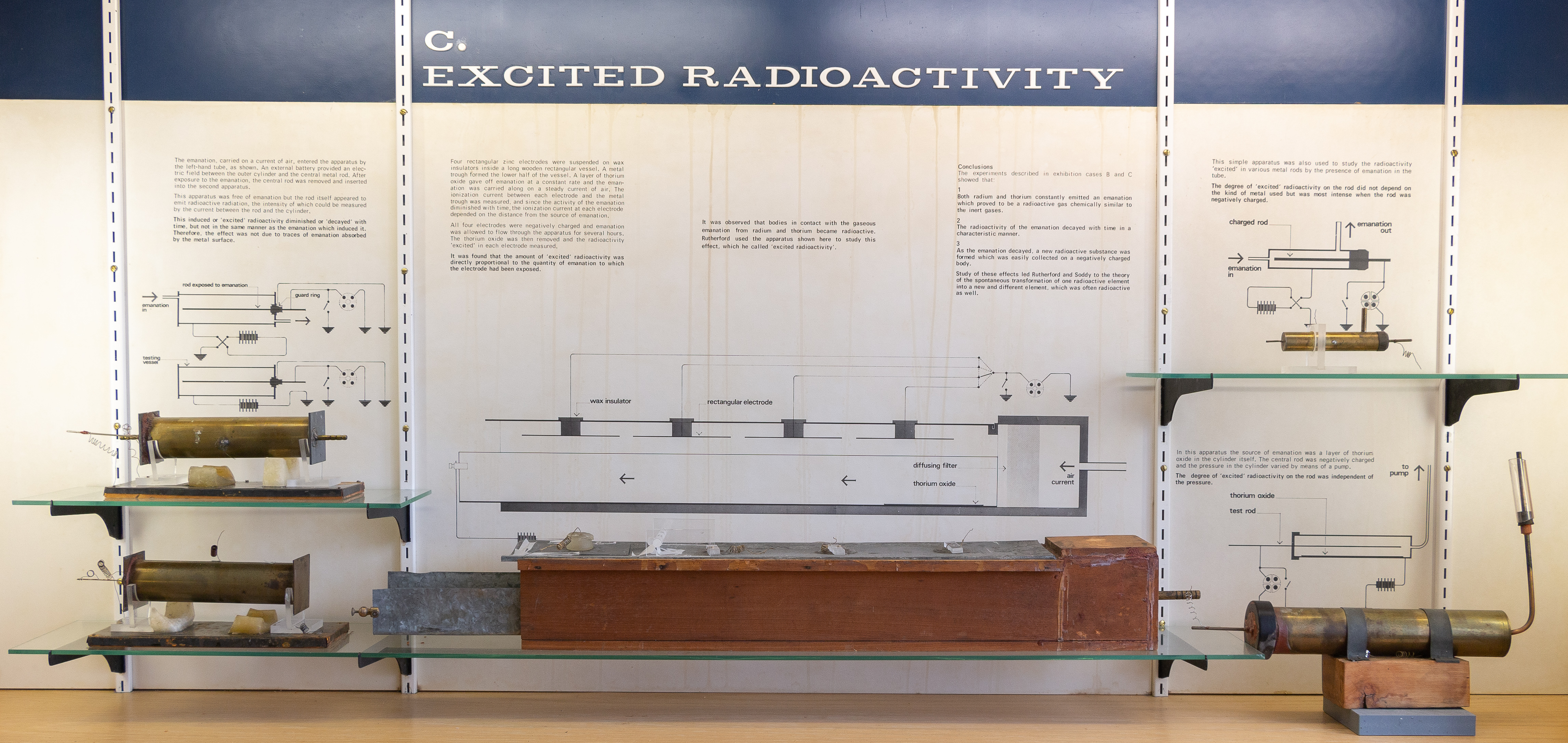
In the summer of 1899 Rutherford observed an unexpected phenomenon: a substance which has been exposed for some time in the presence of thorium is itself rendered radioactive. Rutherford soon ascertained that this is due to the deposition, on the surface of the exposed substance, of an invisible layer of radioactive material. This "excited" radioactivity decays fairly rapidly and disappears within a few days.(Rutherford, 1900, Ref. 25) The excited (or "induced") radioactivity of radium was independently observed by the Curies at about the same time.(26)
C-1. Relationship of emanation and excited radioactivity (Fig. 12):
A current of air containing radium emanation (obtained by heating radium in a platinum cylinder) was passed through a cylindrical ionization chamber. The openings of the chamber were then closed and the ionization current due to the emanation was measured, with a P.D. of 300 V across the chamber (central electrode negative). After several hours the excited activity on the central electrode reached a maximum, and the rod was then removed and placed in an identical chamber, so that the ionization due to the excited activity could be measured, together with its rate of decay. At the same time a fresh central rod was put into the first chamber and the ionization due to the emanation was measured. For radium-C [bismuth-214] the ionization due to the excited radiation was found to be about 50% greater than that due to the emanation which causes it, but for radium-E [Bi-210] the excited radiation was only about half that due to the emanation.(Rutherford and Brooks, 1902, Ref. 27)
C-2. Excited Radioactivity produced by thorium emanation (Fig. 13):
The apparatus comprised a rectangular wooden vessel, 60 cm in length, with a single U-shaped anode and four independent cathodes. A layer of thorium oxide (covered with paper) was placed at one end, and a steady current of air (about 12 cm per min.) passed through. The current due to the emanation was measured at each electrode and, since thorium emanation has a half-life of about 1 minute, the currents at electrodes B, C and D were only 55, 18 and 7 percent respectively of that at electrode A. After 7 hours the flow of air containing emanation was stopped and the ionization current due to the excited activity on each electrode was measured. This was found to be approximately proportional to the current due to the emanation in each case.(Rutherford, 1900, Ref. 28)
C-3. Dependence of excitation on metal and sign of charge (Fig. 14):
The apparatus comprised a small cylindrical ionization chamber, with a removable central electrode. The activity excited by a flow of emanation was measured on central electrodes of various metals, and with this electrode charged positively and negatively. It was found that: (a) the excited radioactivity was independent of the nature of the electrode, but (b) this activity was greatest when the electrode was negatively charged.
C-4. Dependence of excitation on pressure (Fig. 15):
The apparatus comprised a brass cylinder with an ebonite stopper through which passed a brass rod. The cylinder was connected to a mercury pump. Thorium oxide in a paper envelope was placed inside the cylinder. The apparatus was rapidly exhausted to the required pressure and the rod exposed for several hours. The rod was then removed and placed in another ionization chamber so that its radioactivity could be measured. The results showed that the excited radioactivity is independent of the pressure, at least down to 16 mm Hg, although the excitation decreases at very low pressure.(Rutherford, 1900, Ref. 28)


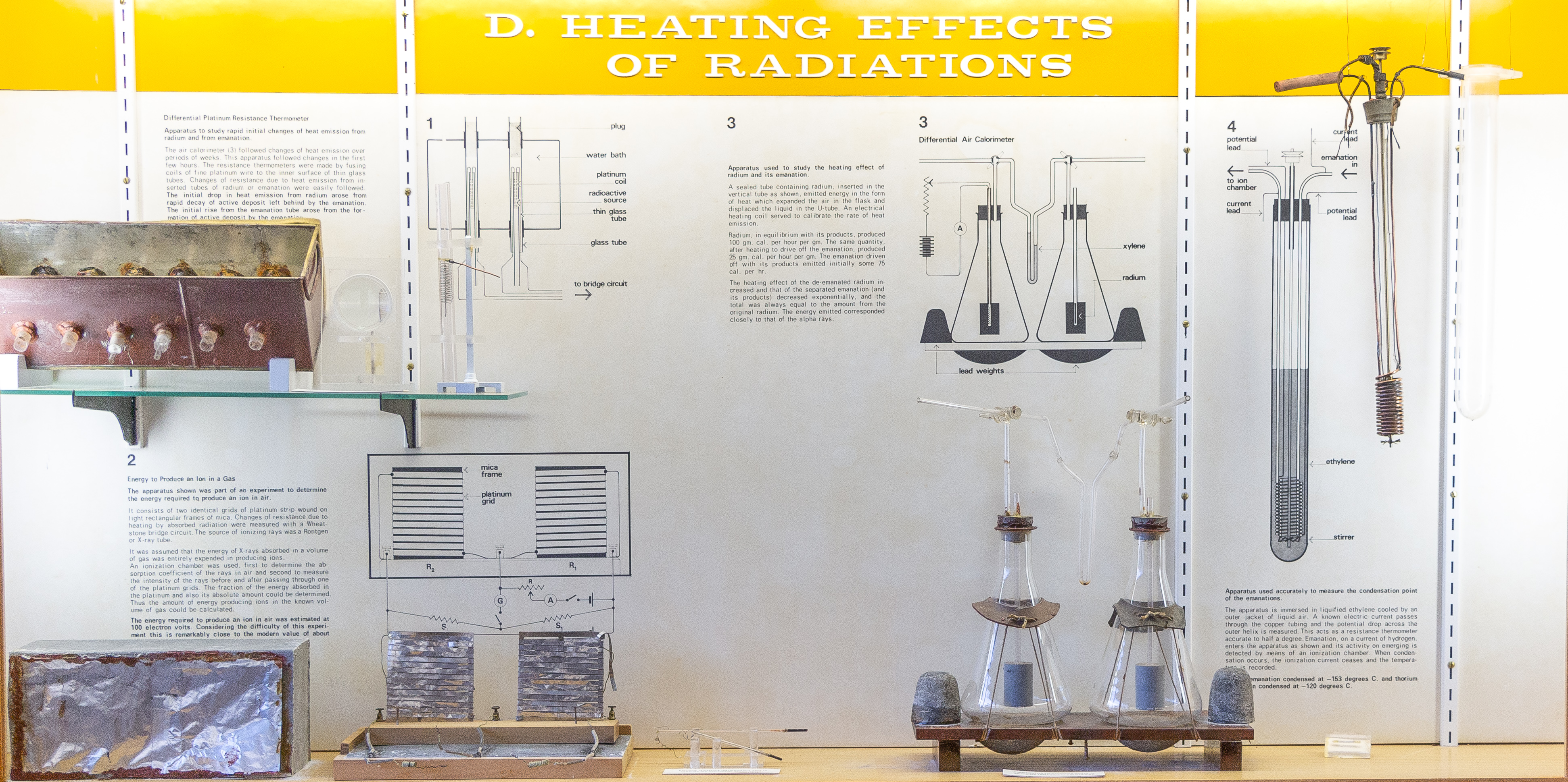
This cabinet contains three pieces of apparatus which Rutherford used to study the energy involved in radioactive transformations and in the production of an ion in a gas. The differential air calorimeter (Exhibit E-3) was used for long term observations, over several weeks, but did not respond quickly enough to measure the initial changes (in a few hours) involved in the decay of emanation and the production of excited radioactivity. For these effects Rutherford and Barnes constructed a number of sensitive platinum resistance thermometers (Exhibit E-1), which responded to temperature changes within 6 or 7 minutes. The fourth item in this cabinet belongs more appropriately to Cabinet B (but there is no room in that cabinet) since it concerns the condensation points of the emanations from radium and thorium.
E-1. Differential platinum resistance thermometer (Figs. 21, 22):
Resistance thermometers were made by fusing coils of fine platinum wire on the inside of thin glass tubes 5 mm in diameter. Each coil was about 3 cm long. Tubes containing radium or emanation were made to slide into the interior of the coil so that the resistance wire was in direct contact with the glass envelope containing the source of heat. The water bath was kept at a uniform temperature by stirring. Changes in the resistance of a thermometer (relative to its neighbor) when a radium or emanation tube was inserted were measured by means of a bridge circuit. The greatest difference in observed temperature was 0.3°C, but readings could be made down to 0.003°C. The initial drop in heat emission from radium was due to the rapid decay of the active deposit left behind by the emanation. The initial rise from the emanation arose from the formation of an active deposit by the emanation.(Rutherford and Barnes, 1904, Ref. 35)
E-2. Energy required to produce an ion in air (Figs. 23,24):
The apparatus shown was part of an experiment to determine the energy required to produce an ion in air. Two identical strips of platinum, each 3 m long and 5 mm wide were wound on mica frames 10 cm square. One grid, A, was irradiated by X rays for a given time, as in Fig. 24, and the change in resistance of grid A compared with grid A' (unirradiated) was measured by a Wheatstone bridge. The resistance change was calibrated, in terms of heating effect, by passing a known current through the coil for the same period as the X-ray exposure. The ionization chamber D (not exhibited) was used to determine the absorption coefficient of the X rays in air and, secondly, to measure the intensity of the rays before and after passing through the grid A. The fraction of the energy absorbed in the platinum, and its absolute amount, could be determined and thus the amount of energy producing ions in the known volume of air could be calculated. It was assumed that the X-ray energy absorbed in air was entirely expended in producing ions. This experiment gave a value of 100 electron volts as the energy required to produce an ion in air. (The modern value is ~ 34 eV.)(Rutherford and McClung, 1901, Ref. 36)
E-3. Heating effect of radium and its emanation (Fig. 25): This apparatus (a differential air calorimeter) comprised two identical glass flasks, connected via a manometer and immersed in a constant-temperature water bath. A sealed tube containing a known mass of radium, or its emanation equivalent, was inserted in the vertical tube in the right-hand flask. The radiation emitted caused a rise in temperature, and hence an expansion, of the air in this flask and thus a displacement of the xylene in the manometer. This displacement was calibrated by means of a measured current in a known resistance wire in the left-hand flask. Initially these measurements were made without the lead cylinders in the flasks, but the apparatus was later redesigned to include the lead so as to absorb the γ-rays as well as the α and β-rays. (In fact the energy contribution of the γ-rays was shown to be only a few percent of the total.)
The experiment showed that 1 gram of radium, in equilibrium with its products, produced 110 gram-calories per hour, of which more than two-thirds was due the emanation stored up in the radium. The heating effect of radium from which the emanation had been expelled was found to increase exponentially, while that of the separated emanation (and its products) decreased exponentially, and the total was always equal to the amount from the original radium before de-emanation. The energy emitted corresponded closely to that of the α-rays.(Rutherford and Barnes, 1904, Ref. 35)
Rutherford and Barnes concluded that "matter under special conditions is capable of emitting an amount of energy enormous compared with that released in the most intense chemical reactions... this energy is derived from the energy latent in the radium atoms, and is released in the successive stages of their disintegration."(35)
E-4. Measurement of the condensation points of the emanations (Fig. 26):
This apparatus links with Exhibit B1/B2, which Rutherford and Soddy used to demonstrate that thorium emanation could be liquefied and was therefore a true gas. Exhibit E-4 was used to measure the precise condensation points of both thorium and radium emanations. Thin copper tubing of internal diameter 2 mm was wound into an inner spiral of mean diameter 1.8 cm and an outer spiral of mean diameter 2.9 cm. The turns of the outer spiral were separated from each other and from the inner spiral by air spaces. The outer spiral constituted a thermometer: with a constant current of 0.90 mA, the voltage across the spiral dropped from ~ 6 mV at room temperature to less than 2 mV at the temperature of liquid air. The purpose of this arrangement was to subject the gas (emanation) stream to a preliminary cooling to the desired temperature in order to ensure that the measuring (outer) spiral was not heated locally by the entering gas stream. The liquid used in the tube was liquefied ethylene, which is liquid between -104° and -169°C. As indicated in Exhibit B1/B2, the condensation point of the emanation was determined by the cessation of the reading of the ionization chamber into which the stream of gas was directed after leaving the outer copper spiral. The condensation points thus determined were -120°C (thorium emanation) and -150°C (radium emanation).(Rutherford and Soddy, 1903, Ref. 19)


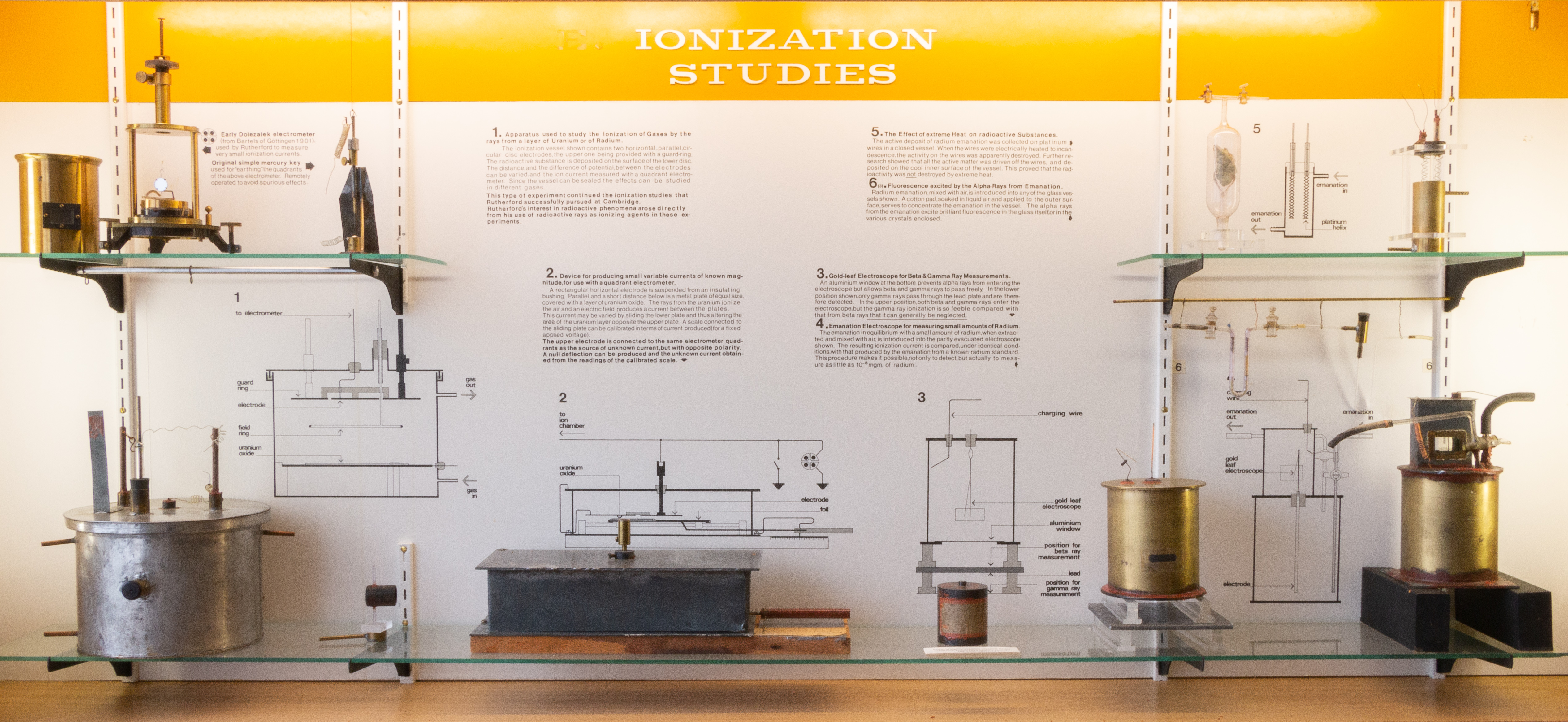
This cabinet contains a number of pieces of apparatus used for the study and measurement of α and β-rays. Two unnumbered items are the Dolezalek quadrant electrometer and the remote-control key (Fig. 4) which were discussed earlier under "Measurement techniques." In addition, there are two exhibits (D-5 and D-6) concerned with other properties of radioactivity (effect of heat on excited radioactivity; and fluorescence excited by α-rays).
D-1. Apparatus for the study of ionization in different gases (Fig. 16):
The ionization was produced by a thin layer of uranium or radium on the lower plate. The distance and potential between the parallel electrodes could be varied, and the potential at intermediate distances was measured by a wire loop (potential ring) connected to an electrometer, and could be adjusted to zero by means of the rheostat. The ionization current was always greater when the lower plate was negative rather than positive. The ionization current was determined for dry and moist air, and after the introduction of alcohol vapor or the vapor of methyliodide.(Rutherford, 1901, Ref. 29)
D-2. Device for producing variable currents of known magnitude (Fig. 17):
As mentioned above, under "Measurement techniques," there was a need for a method of producing a constant deflection of the electrometer proportional to radiation intensity, for the study of radioactive elements which decayed very rapidly. The instrument exhibited solved this problem by balancing the unknown ionization current against a current generated in a second parallel-plate chamber in which the lower plate was coated with a layer of radioactive material (uranium oxide) of long half-life. The area of uranium opposite the upper electrode was varied by sliding the lower electrode, to which a calibrated scale was attached. The upper electrode was connected to the same electrometer quadrants, but with opposite polarity, as the source of unknown current to be measured, and a null reading obtained by sliding the lower electrode.(Bronson, 1905, Ref. 8; Allen, 1907, Ref. 9)
D-3. Gold-leaf electroscope for β and γ-ray measurements (Fig. 18):
The aluminum window at the bottom of the electroscope absorbed α-rays but allowed β and γ-rays to pass freely. With the source in the upper position both β and γ-rays entered the electroscope but the γ-ray ionization was negligible compared with that of the β-rays. For γ-ray measurements the source was placed under a lead plate 6 mm thick which completely absorbed the β-rays but allowed the γ-rays to pass. (Rutherford, 1904, Ref. 30)
D-4. Emanation electroscope for measuring small amounts of radium (Fig. 19):
The emanation in equilibrium with an unknown small amount of radium was extracted, mixed with air and introduced into the party evacuated electroscope. The resulting rate of fall of the gold leaf was compared with that produced, under the same conditions, by the emanation from a radium standard. As little as 10-8 mg of radium could be measured by this technique.(Rutherford, 1913, Ref. 31)
D-5. Effect of heat on excited radioactivity (Fig. 20):
The active deposit of thorium emanation was collected on a platinum helix in a closed vessel. When the wire was electrically heated to incandescence the activity was apparently destroyed. However, further investigation showed that the active deposit was not destroyed but simply driven off the wire and deposited on the cool inner surface of the vessel.(Rutherford, 1902, Ref. 32)
D-6. Fluorescence excited by α-rays:
Three separate glass vessels containing various crystals are shown. These crystals include zinc sulfide, barium platinocyanide, diamond, uranium-potassium sulfate and calcium fluoride. Radium emanation, mixed with air, was introduced into the vessels. A cotton pad, soaked in liquid air and applied to the outer surface of the glass, served to condense and therefore concentrate the emanation. The α-rays from the emanation excited brilliant fluorescence of various colors, in the glass or in the crystals enclosed. The effect is due mainly to the α-rays, as Rutherford showed (in a separate experiment) but interposing a paper screen between a radium source and the crystals. [N.B. Strictly speaking, this phenomenon is phosphorescence rather than fluorescence, since the emission of light continues after the exciting radiation is withdrawn.] (Becquerel, 1899, Ref. 33; Rutherford, 1904, Ref. 34)


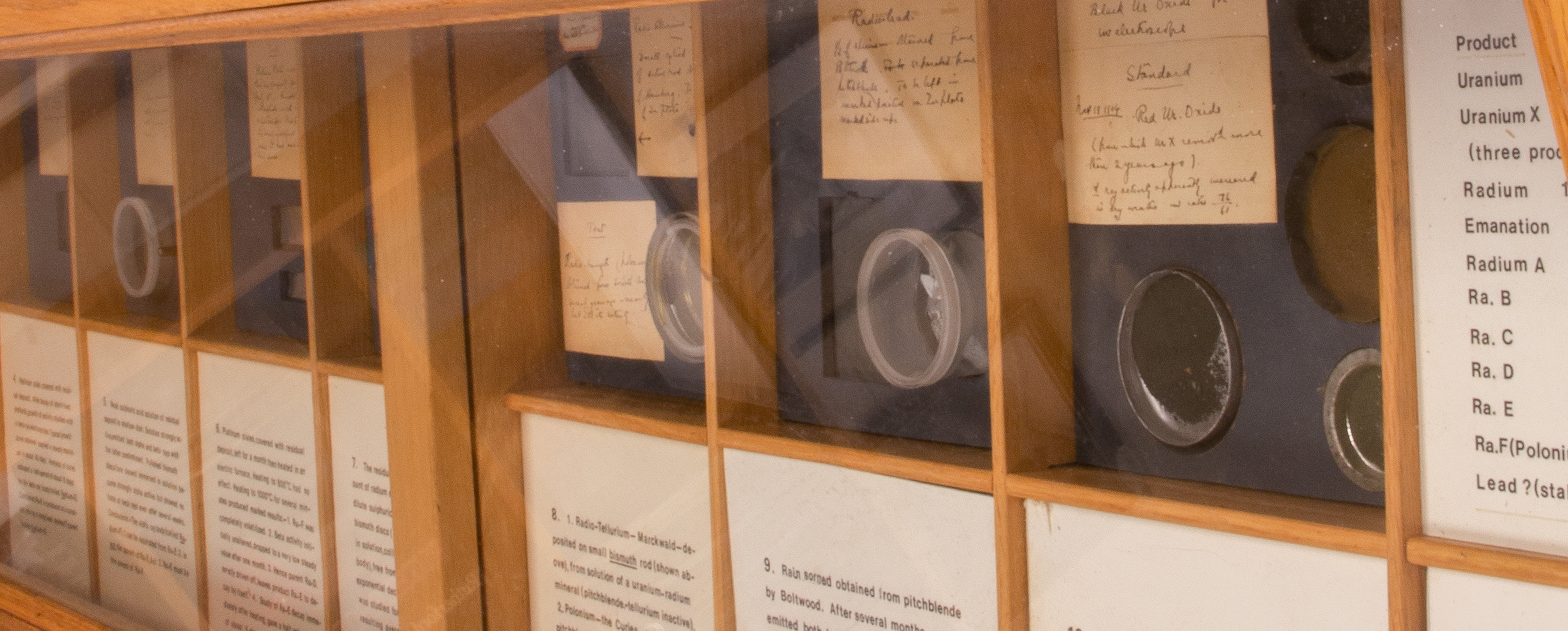
This display cabinet houses two separate exhibits. On one side is a series of 12 sections showing the materials (as distinct from apparatus) used by Rutherford in July-December 1904 to elucidate the decay series of radium beyond the stage of the "excited" radioactivity discussed in Cabinet C. Each of these sections includes original dated labels in Rutherford's handwriting.
Rutherford suspected that some activity persisted after the decay of the short-lived deposit and he carried out a series of experiments to investigate this problem. For example (in the first section) 6 equal plates of different metals were exposed to emanation (radon). After several weeks, all the plates showed equal traces of residual activity which increased at least 3-fold within a month. Rutherford concluded that there must be a common active deposit rather than an "induced effect," and the gradual increase suggested the presence of a "rayless" parent body.
As a result of these experiments Rutherford identified three decay products which he designated as radium-D, E and F.
Rutherford found no evidence of active products beyond Ra-F. The atomic weight of radium was 225(Curie, 1902, Ref. 37) and its products emitted 5 a particles (Ra, Rn, Ra-A, Ra-C, Ra-F). Assuming that the a particle was a helium atom of atomic weight 4, Rutherford concluded that the end-product of the radium series had an atomic weight of 205. This was so close to that of lead (206) that it appeared most probable that the final product of radium was stable lead.(Rutherford, 1904, Ref.38; 1905, Ref. 39)
On the other side of this cabinet a number of documents are displayed, as follows:
Rutherford, 1904-1905 |
Today |
|---|---|
Ra-D (Pb-210) T½ = 40y; "rayless" |
21y; b |
Ra-E (Bi-210) T½ = 6d; b |
5d; b |
Ra-F (Po-210) T½ = 143d; a |
138d; a |