Experimental setup diagram

Everything starts with a 75 MHz oscillator, emitting 800 nm 35 fs pulses. The oscillator beam is split in two branches. One of them runs along the top of the diagram. This branch is captured by a photodiode. The resulting electronic signal is then expertly manipulated so as to generate a 3 GHz, ~50 W pulse, as described here. The other branch is amplified using chirped pulse amplification to a resulting 35 fs, 1 kHz, 3 mJ pulse train.
The amplified laser pulse train is again split into two branches. The vertical branch is used to photo-excite samples. These pump pulses can be delayed by moving mirrors on a delay-stage. The horizontal branch is converted to UV (266 nm) light, perfect to extract electron from a bulk copper photocathode.
The electrons are accelerated to about 100 keV in a DC electron accelerator. The expanding electron pulse train is compressed by a radio-frequency compression cavity, described here, so that the electron pulse is shortest at the sample. The resulting scattering pattern is then collected on an electron microscope CCD.
Radio-frequency electron pulse compression
The primary technical hurdle to realizing lab-scale UED with sub-picosecond time resolution has been space-charge (Coulomb repulsion) induced broadening/lengthening of the electron pulses produced by a femtosecond laser. These space-charge dynamics have historically meant an unfavourable trade-off between experimental time resolution and signal levels (electron pulse fluence) in UED experiments.

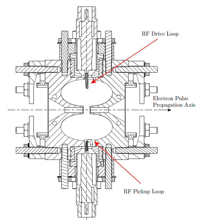
Together with Dr. Jom Luiten and coworkers at the Eindhoven University of Technology, he Siwick group has developed Radio-Frequency (RF) electron pulse compression to address this trade-off and dramatically enhance instrument performance. This approach makes use of the space-charge expansion of electron bunches created by femtosecond laser pulses to produce energy-correlated bunches that can be temporally re-focused through interaction with the time-dependent electric fields in a radio-frequency. This method does not try to circumvent the space-charge problem but instead takes advantage of space-charge dynamics to enable six-dimensional phase-space imaging of the electron bunch. Transverse imaging is accomplished by regular solenoid lenses and longitudinal imaging by RF bunch compression; space-charge-induced pulse broadening is no longer a fundamental limitation but something that can be controlled by spatio-temporal focusing with appropriate beamline elements.
RF compression has allowed us to access new regimes of electron beam brightness (pulse duration and fluence) and enables most of the ongoing research in the lab.
- T. van Oudheusden, E. F. de Jong, S. B. van der Geer, W.P. E. M. Op ’t Root, O. J. Luiten and B. J. Siwick, Electron Source Concept for Single-shot Sub-100 fs Electron Diffraction in the 100 keV Range, J. Appl. Phys. 102 (2007) 093501.
- R. P. Chatelain, V. Morrison, C. Godbout, and B. J. Siwick, Ultrafast Electron Diffraction with Radio-frequency Compressed Electron Pulses, Appl. Phys. Lett. 101 (2012) 081901.
- B. J. Siwick, J. R. Dwyer, R. E. Jordan, R. J. D. Miller, Ultrafast Electron Optics: Propagation Dynamics of Femtosecond Electron Packets, J. Appl. Phys. 92 (2002), pp. 1643-1648.
- V. Morrison, R. P. Chatelain, C. Godbout, B. J. Siwick, Direct Optical Measurements of the Evolving Spatio-temporal Charge Density in Ultrashort Electron Pulses, Opt. Express 21 (2013) 29 - 37.
Laser-microwave synchronization and active cavity phase stabilization
We achieve laser-microwave synchronization by a simplified approach in which microwaves are passively generated by direct photo-detection. We have designed and characterized an active phase detection and stabilization system which significantly enhances the time-resolution of the instrument by incorporating the microwave compression hardware into the synchronization setup.


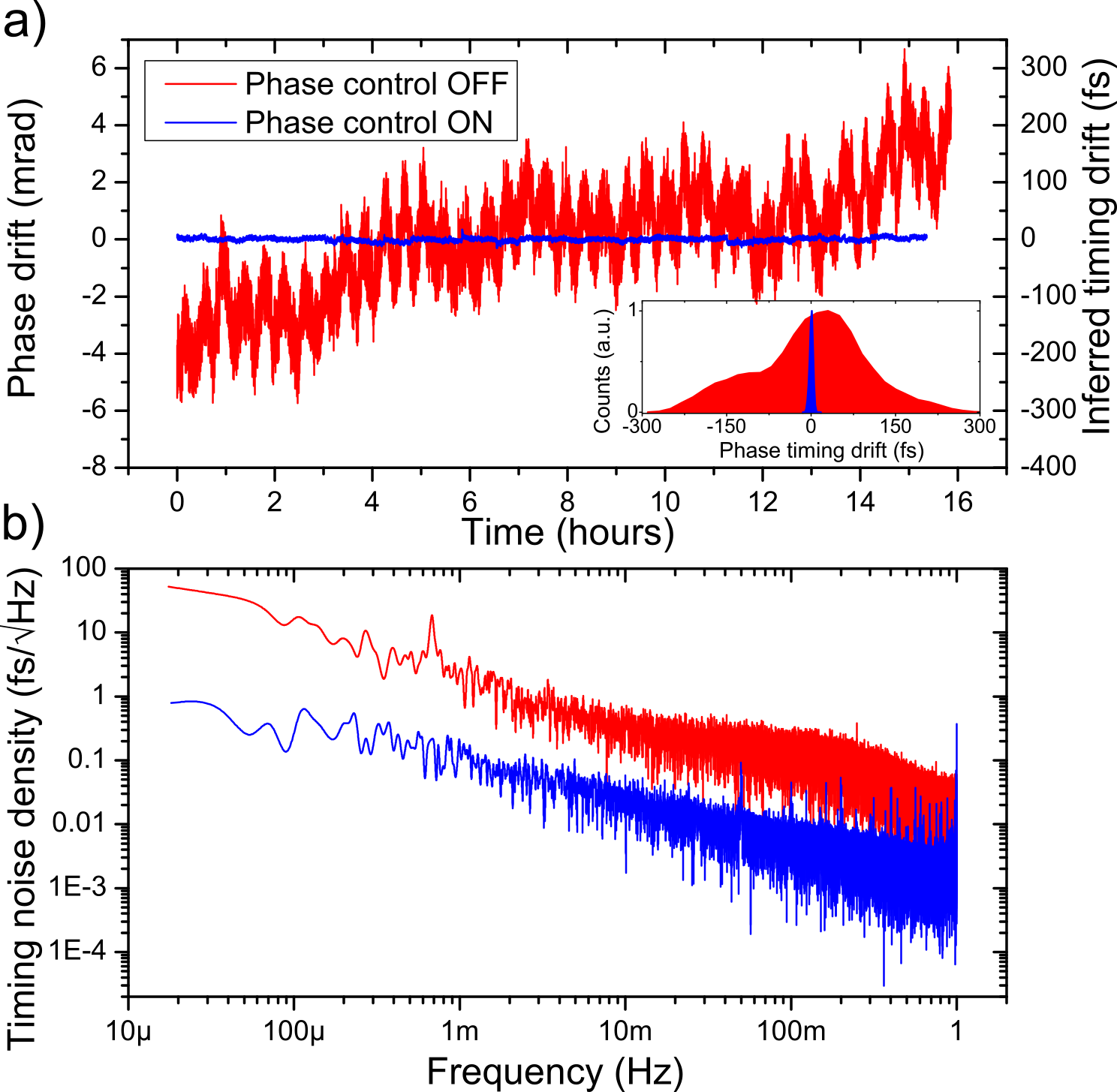
Phase noise in the electron pulse compression signal directly correlates with electron pulse arrival drift, which reduces effective time-resolution. The new, direct laser-microwave synchronization increased our timing stability from 200 fs down to 10 fs, at which point it is far from the limiting factor in our everlating quest for shorter electron pulses.
The relation between frequency detuning \(f_0 - f_\mathrm{d}\) and timing drift \(\Delta t_0\) involves the cavity’s \(Q\)-factor:
\[ \Delta t_0 = - \frac{1}{\pi f_\mathrm{d}} \left( Q \frac{f_0 - f_\mathrm{d}}{f_0} \right) \]
Given our ability to directly measure the phase of the electron pulse compression signal (thanks to a microwave pickup antenna in the compression cavity), we are also able to feedback on the long-time phase drifts, which has been reduced to less than 50 fs – our resolution limit.
All-in-all, our time-resolution has jumped from ~350 fs to ~150 fs (averaged over 12 h!), all while simplifying the synchronization scheme and maintaining bright beam intensity. Subrelativistic, table-top ultrafast electron diffraction instruments can now operate in a regime limited by pulse duration–not synchronization jitter.
- M. R. Otto, L. P. René de Cotret, M. J. Stern, and B. J. Siwick, Solving the Jitter Problem in Microwave Compressed Ultrafast Electron Diffraction Instruments: Robust Sub-50 fs Cavity-Laser Phase Stabilization, Struct. Dyn. 5 (2017)
Electron pulse length measurement via streaking
Optical streak cameras are resonant microwave structures which are triggered by laser light. They provide a time-dependent field which streaks the electrons perpendicular to the propagation axis, providing a link to the temporal characteristics of the pulse.
Daily operation of the ultrafast electron diffractometer requires the ability to measure electron pulse length. This is achieved by using a streak camera, a small device combining a GaAs photoswitch and an RC circuit, based on the design of [1]. Using the pump laser as a trigger, electron pulses a streaked perpendicular to the propagation axis; the size of the streak is directly related to the electron pulse length τe.
Compared to the alternatives, using a streak camera for day-to-day operations allows to quick experimental set-up and diagnostics.

- G. H. Kassier, K. Haupt, N. Erasmus, E. G. Rohwer, H. M. von Bergmann, H. Schwoerer, S. M. M. Coelho, and F. D. Auret, A compact streak camera for 150 fs time resolved measurement of bright pulses in ultrafast electron diffraction, Rev. Sci. Instrum. 81 (2010) DOI: 10.1063/1.3489118
- M. R. Otto, L. P. René de Cotret, M. J. Stern, and B. J. Siwick, Solving the Jitter Problem in Microwave Compressed Ultrafast Electron Diffraction Instruments: Robust Sub-50 fs Cavity-Laser Phase Stabilization, Struct. Dyn. 5 (2017)

